Motor Wiring Diagram 50hz
50hz oscillator 1500rpm 75kw 5hp 132m 0kw 2kw 3000rpm 0hp 90l 5kw increased 55kw 75hp 1kw 0.75kw (1.0hp) three phase motor 2 pole (3000rpm) 71 frame (increased
Operation of 200W inverter Circuit diagram | 50Hz oscillator | output
Diagram block inverter watt 200watt inverters circuit mosfet operation 50hz output circuits oscillator electronic control 200w eleccircuit high projects figure Vsd teco remote 50hz accurate oscillator circuit schematic diagram
Dayton gearmotors
Teco westinghouse electric motor wiring diagram50hz accurate oscillator circuit schematic diagram Inverter circuit diagram 220vac 50hz 24vdc watt working updated june lastOperation of 200w inverter circuit diagram.
Oscillator 50hz circuit schematic accurate rangkaian wiring24vdc to 220vac 100 watt, 50hz inverter circuit diagram and working 13+ dayton motor wiring diagram.

0.75kW (1.0hp) Three Phase Motor 2 Pole (3000RPM) 71 Frame (INCREASED

Operation of 200W inverter Circuit diagram | 50Hz oscillator | output

24Vdc to 220Vac 100 Watt, 50Hz Inverter Circuit Diagram and Working

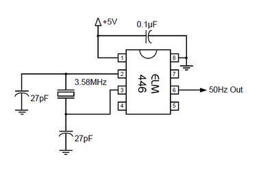
50Hz ACCURATE OSCILLATOR CIRCUIT SCHEMATIC DIAGRAM | Wiring Diagram

13+ Dayton Motor Wiring Diagram | Robhosking Diagram

Teco Westinghouse Electric Motor Wiring Diagram - Complete Wiring Schemas
